Description
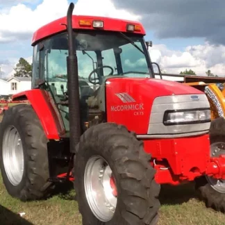
McCormick CX Tractors CX75 CX85 CX95 CX105 Official Service Repair Manual
Exclusive Version !
The Best PDF Manuals Online Includes : Bookmarks + Searchable Text + Index = Fast Navigation And Best Organization !
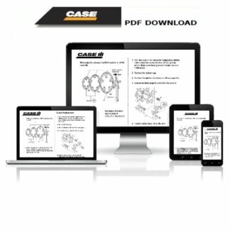
File Format: PDF
Manual Language: English
This is the COMPLETE Official Service Repair Manual for the McCormick Tractor .
This manual contains deep information about maintaining, assembly, disassembly and servicing your Machine .
This PDF file is Bookmarked and SEARCHABLE to make what you need easy to find.
This Manual contains information and data to this model. has specs, diagrams, and actual real photo illustrations, and schemes,
which give you complete step by step operations on repair, servicing, technical maintenance & troubleshooting procedures for your machine.
this manual offers full information you need for repair your machine.
the information in this manual will enable you to find trouble and to understand how to repair and maintain your machine without going into service.
all pages are printable, so run off what you need and take it with you into the garage or workshop.
Models Covered:
McCormick CX75 TRACTOR
McCormick CX85 TRACTOR
McCormick CX95 TRACTOR
McCormick CX105 TRACTOR
Table of Contents:
=========
=========
Fluids and Lubricants
Conversion Table
Abbreviations
Removal and Installation of Engine Assembly
Removal and installation of the fuel cooler engine inter-cooler radiator and oil cooler
Removal and Installation of Turbo Charger
Removal and Installation of EGR Valve
Removal and Installation of Engine Hood
Removal and Installation of Muffler
Primary specifications
Removal and Installation of Cylinder Head
Removal and Installation of Cylinder Block
Lubrication System
Cooling System
Removal and Installation of Exhaust Manifold
Disassembly, Removal and Installation of DPD Assembly
Removal and Installation of Fuel Tank
Removal and Installation of Fuel Supply Pump
Removal and Installation of Common Rail Assembly
Removal and Installation of Injector
Electrical and Engine Basic Functions
Service Support
Function, Structure, Operation
Symptom
Functional Inspection
Maintenance precautions
Removal and Installation of Starter Motor
Removal and Installation of Alternator
Preheating System
Electrical Equipment Layout Diagram
Connection Connector Pin Layout
Sequence Circuit Diagram
Engine-side DTC List
Main Unit-side DTC List
Introduction to the trouble diagnosis
Engine Control System
Engine-side Trouble
Main Unit-side Trouble
Data Reference Values
Electrical Wiring Diagram
Removal and Installation of Shoe Assembly
Removal and Installation of Shoe Plate
Removal and Installation of Upper Roller
Assembly and Disassembly of Upper Roller
Removal and Installation of Lower Roller
Assembly and Disassembly of Lower Roller
Removal and Installation of the Sprocket
Removal and Installation of Take-up Roller
Assembly and Disassembly of Take-up Roller
Removal and Installation of Grease Cylinder
Assembly and Disassembly of Tension Shock Absorber
Removal and Installation of Travel Motor
Assembly and Disassembly of Travel Motor
Removal and Installation of Swing Unit
Assembly and Disassembly of Swing Unit
Overall view
Port Diagram
Pump P-Q Diagram
Pressure Measurement and Adjustment Procedures
Hydraulic Pump Flow Measurement Procedures
Drain Volume Measurement Procedures
Air Bleed Procedure
Removal and Installation of Hydraulic Oil Tank
Removal and Installation of Hydraulic Pump
Removal and Installation of Control Valve
Removal and Installation of Bucket Cylinder
Removal and Installation of Arm Cylinder
Removal and Installation of Boom Cylinder
Removal and Installation of Center Joint
Removal and Installation of Travel Remote Control Valve
Removal and Installation of Operation Remote Control Valve
Removal and Installation of 5 Stack Solenoid
Removal and Installation of Cushion Valve
Procedures for Assembly and Disassembly of Hydraulic Pump Main Unit
Pump Main Unit Maintenance Standards
Procedures for Assembly and Disassembly of Control Valve
Procedures for Operation/Assembly and Disassembly of Hydraulic Cylinder (made by KYB)
Procedures for Assembly and Disassembly of Operation Remote Control Valve
Procedures for Assembly and Disassembly of Travel Remote Control Valve
Assembly and Disassembly of Cushion Valve
Removal and Installation of Arm HBCV
Removal and Installation of Boom HBCV
Assembly and Disassembly of Center Joint
Assembly and Disassembly of Swing Motor
Explanation of Hydraulic Circuit and Operations (standard model)
Explanation of Hydraulic Circuit and Operations (option)
Structure and Operation Explanation of Hydraulic Pump
Structure and Operation Explanation of Travel Motor
Structure and Operation Explanation of Swing Motor
Structure and Operation Explanation of Control Valve
5 Stack Solenoid Valve Operation Explanation
Structure and Operation Explanation of Upper Pilot Valve (remote control valve)
Structure and Operation Explanation of Travel Pilot Valve (remote control valve)
Structure and Operation Explanation of Cushion Valve
Removal and Installation of Counterweight
Removal and Installation of Bucket
Removal and Installation of Bucket Link
Removal and Installation of Arm
Removal and Installation of Boom
Removal and Installation of Operators Seat
Removal and Installation of Cab Assembly
Removal and Installation of Wiper
Removal and Installation of Wiper Controller
Removal and Installation of Wiper Motor
Removal and Installation of Monitor
Removal and Installation of Cab Front Glass
Window Lock Adjustment Procedures
Tightening torque
Air Conditioner Overall Diagram
Assembly and Disassembly of Air Conditioner Units
Removal and Installation of Compressor
Removal and Installation of Condenser
Removal and Installation of Receiver Dryer
Work Precautions
Electrical Schematic
Hydraulic Schematic
===========
Product Details :
File Format: PDF
Compatible: All Versions of Windows & Mac
Language: English
Requirements: Adobe PDF Reader
===========